Analog Data Storage
Although the method of storing the analog sample values is different between the Integer and Floating-point versions of the C3D file format, both versions organize the individual analog data samples in the same way within the 3D Data section of the C3D file. The analog record for each 3D frame can contain one or more analog data samples where each analog data sample consists of one or more analog measurements (channels) usually recorded from an ADC (analog to digital converter) during the 3D frame sample period. The parameter ANALOG:RATE stores the total number of analog data samples per 3D frame while the parameter ANALOG:USED stores the number of analog measurements, or channels, within each analog data sample. All of this data is recorded at a 3D frame rate whose value is recorded in the POINT:RATE parameter.
The C3D file format is designed to store synchronized 3D data and analog data; 3D measurements are recorded at fixed intervals (set by the POINT:RATE parameter) and multiple analog samples, recorded at fixed intervals within each 3D frame, are stored with each 3D frame in the 3D/Analog data section of the C3D file. For example, if the 3D data is sampled every 20ms (50Hz frame rate) and each 3D frame has 5 analog samples then the analog data is sampled every 2ms within the 3D frame.
Thus, when analog data is present in the C3D file, each 3D frame is followed by one or more analog samples for each analog channel. These are organized as shown below where “N” is the number of analog measurements per 3D frame (stored in word 10 of the C3D file header), and “n” is the number of analog channels that are stored in the C3D file. The number of channels sampled is not stored in the C3D header directly but can be calculated as (Word 3) / (Word 10) or (total analog samples per 3D frame) / (number of samples per analog channel) or read from the parameter data section:
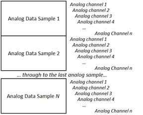
Figure 29 - The organization of N samples of n channels analog data
For example, consider a C3D file that contains 3D point information that has been recorded at 60Hz, and contains 18 analog channels that have each been sampled at a rate of 1200 samples per second. This information is stored in the C3D file in the following parameters:
POINT:RATE = 60
ANALOG:USED = 18
ANALOG:RATE = 1200
Thus the analog data will be written with each individual analog record containing eighteen values – one value per analog channel recorded in the ANALOG:USED parameter. Each analog channel is sampled twenty times per 3D frame of data and there will be sixty 3D frames per second as recorded in the POINT:RATE parameter. The C3D file does not directly store the number of analog data samples per frame as a parameter; this value is calculated by dividing the ANALOG:RATE value by the POINT:RATE value. So each 3D frame of data recorded at 60Hz will contain twenty sets of analog samples, each recording eighteen analog channels.
The number of analog data samples per 3D frame value is stored in word 10 of the C3D file header, together with a count of the total number of analog samples per 3D frame in word 3, so that the analog data can be quickly read by any application that opens a C3D file without having to read and interpret values from the parameter section of the C3D file.
The synchronization, or timing accuracy of the 3D and analog data, depends on the hardware data collection system and the signal latency of any devices connected to the analog sampling system. While the C3D format is capable of recording 3D and analog data with perfect synchronization, analog devices connected to a 3D data collection system by a USB interface, may have significant signal latencies that can result poor synchronization of the recorded data.
It is the responsibility of the Motion Capture system to document the latencies of each of the sensors being sampled and remove any delays from the data when the C3D file is created. Any temporal processing of the data should be recorded in the file parameters, documenting the manipulation of the data so that any subsequent analysis of the data knows what has been done.
Users can verify the system synchronization by applying a common input signal to each sensor simultaneously. For example, place a small loudspeaker or microphone, connected to an EMG input, on a force plate, and then drop a golf ball, covered in retro-reflective tape or attached to a marker onto the plate. The marker trajectory will change as it strikes the force plate, generating a small vertical force signal and the loudspeaker or microphone will record the impact via the EMG input at the same instant – resulting in a C3D file with one common stimulus recorded through each sensor as shown below:
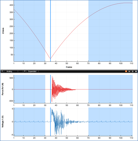
Figure 30 - A synchronization test showing a 3D trajectory, force vector, and EMG input.
The synchronization test illustrated above was performed with a high 3D frame rate of 250 frames per second and eight analog samples per frame. The high sample rates allow the data collection to measure the force plate signal latency of 4ms (one 3D frame) and the EMG signal latency of 3.75ms.
This test allows the individual sensor latency to be determined, but the overall the data collection synchronization accuracy needs a second test, dropping the golf ball again after a typical trial period. If the data collection sampling rate is accurate then both tests, at the start of the data collection and the end of the data collection, will result in identical measurements.
Any difference in the measurements at the start of the trial and the measurements at the end of the trial indicate that the 3D point sample rate and the analog sample rate were not accurately synchronized when the data was sampled and the file created. This may be a result of the recorded 3D sample rate data being set to 60Hz, with the 3D samples recording in synchronization with video data recorded at 59.94Hz which results in a 16us synchronization error in the second frame in the C3D file, an error of 0.5ms (16us*60) after one second, increasing to an error of 58ms (16us*60*60) at the end of a one minute trial.
 Analog Data - Integer Format