Description
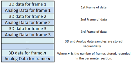
All related 3D point and analog data samples are written as sequential frames starting in the 512-byte block in the C3D file specified by the POINT:DATA_START parameter. If each frame contains both 3D point and analog information then the 3D point data is written first, starting with the first frame of data, followed by multiple analog data samples associated with the 3D frame. If there is only a single type of data (either 3D point data, or only analog data) then the data section will simply consist of sequential frames of data samples.
The POINT:DATA_START parameter is an unsigned 16-bit integer that points to the location of the start of the 3D/analog data section within the C3D file, allowing the 3D/analog section to start anywhere within the first 32Mb (65535*512/1024) of the C3D file.
3D point locations and analog data samples may be stored in either signed 16-bit integers or 32-bit floating-point format. Whichever method is selected applies to both the 3D point and the analog data records within the C3D file. If the 3D point data is stored in floating-point format, then the analog data must also be stored in floating-point format. It is not possible to mix data storage types within a C3D file, as there is only a single flag (the sign of the POINT:SCALE parameter) that indicates which storage method is used.
Since the number of frames within each C3D file is stored in the C3D file parameter section as POINT:FRAMES, there is no need for an “end-of-data” marker - data is simply written from the first frame to the last frame. It is recommended that any unused storage in the final 512-byte block of the C3D file should be filled with 0x00h.

Figure 21 - The 3D/analog data storage structure.
The C3D file format requires that 3D point data values, defined by the POINT:USED parameter, will be written to the each frame within the 3D data section in the order that they are listed in the POINT:LABELS parameter section. As a result, applications that access the 3D point data must determine the storage order and identity of the 3D points by reading the order of the point labels stored in the parameter section each C3D file. The analog samples in each 3D frame are recorded sequentially as listed by the ANALOG:LABELS parameter section and defined by the ANALOG:USED and ANALOG:RATE counts.
The existence of a single point of 3D data in only one frame of a C3D file requires that storage space for this point be allocated in every single frame of the C3D file. This can result in files with a large amount of wasted space if unused, short trajectories are preserved unnecessarily. There is normally no need to record noise, unidentified 3D trajectories, brief marker appearances that have no significant value, or analog channels that have no valid signal or data because this fills both the 3D data and parameter sections with information that must be read and processed before being discarded by any application reading the C3D file.
Analog channels are stored in sequence starting with the first sampled analog channel, which is always channel one. If ten analog channels are sampled once per 3D frame, then the ten analog values are written in sequence after the 3D point data, starting with channel one and ending with channel ten. If there are three samples of analog data per 3D frame then the first ten analog samples will written in sequence, followed by the second set of analog samples and finally the third set of ten analog samples. This will be followed by the next frame of 3D data which will be followed by the next three sets of analog samples associated with the 3D data frame.
It is worth observing here that analog channels are usually stored in sequence starting with the channel one. There is no provision, in the C3D format, to store only ADC channels 2, 8, and 10 and identify them as such – in order to store channel 10 all the channels between 1 and 10 be stored. However, since analog channels can be referred to by their ANALOG:LABELS assignments, there is no need to store unused analog channels if applications use the ANALOG:LABELS parameter to identify channels instead of the physical channel number to identify the individual analog channels. Thus a C3D file could store only the three channels, each identified by a unique LABELS parameter as C3D analog channels 1, 2, and 3. Applications would then reference each channel by its LABELS, not its original physical channel number.
Both analog channels and 3D points stored within the C3D file format are indexed and counted from base “one” – this can occasionally lead to confusion when sampling data from an analog data collection system that counts channel “zero” as the first analog channel. There is no “Frame 0” or “Analog Channel 0” in a C3D file, the first frame of 3D data is always counted as Frame 1 and the analog channel count always starts with Channel 1.
 3D Data - Integer Format