ANALOG:SCALE
The individual ANALOG:SCALE values exist to scale each analog data channel and are applied to the scaling calculations regardless of the C3D file format. Setting both the ANALOG:GEN_SCALE value and the individual ANALOG:SCALE value to 1.00 effectively removes the scaling factors from the C3D file and is normal when the recorded analog data values are pre-scaled and stored in a floating-point formatted file. Note that this will prevent the analog data being preserved if the C3D file format is ever changed from floating-point file to an integer formatted file without rescaling all of the data.
The ANALOG:SCALE parameter is an array of floating-point values that are applied (together with the ANALOG:GEN_SCALE parameter value) to convert the analog data to physical world values – normally the units described in the ANALOG:UNITS parameter. As a result, it is essential that each analog channel have an associated SCALE parameter together with an OFFSET parameter so that the correctly scaled analog values can be calculated. The scale calculation applies to both Real (floating-point) and Integer formatted C3D files.
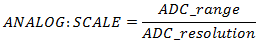
The ANALOG:SCALE parameters convert the analog values stored in a C3D file into volts measured at the ADC inputs via a simple calculation:
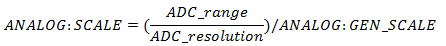
The ANALOG:GEN_SCALE parameter may be used to apply an additional uniform scale factor to all analog channels. In these discussions it will be assumed that ANALOG:GEN_SCALE = 1.0 and therefore has no effect on the results although we will show it in the calculations thus:
The ADC_range is the actual input range of the ADC card that is used to collect the data. This is normally ±10Volts, which yields an actual ADC_range of 20 Volts which implies that the ADC card can record signals over the range of 10 volts negative to 10 volts positive magnitude, a total range of 20 Volts.
While the default ADC_range is normally 20 Volts, it is common for individual ADC channels for have the ability to select lower ranges by programming a fixed gain within the ADC measurement system for each individual analog channel. An individual channel gain of x2 results in an individual ADC_range of 10 Volts (±5Volts) while a gain of x4 results in an ADC_range of 5 Volts (±2.5Volts). It is best to always think of this change as a change in the range of acceptable ADC input voltages to avoid confusing the individual ADC channel gains with other external equipment gains. It is very important to remember that any signal that exceeds the ADC input range limits will always result in a clipped signal and the loss of data.
The variable ADC_resolution is the total number of discrete measurement steps available to measure the ADC input signal, which is related to the ADC precision. An ADC with 12-bit precision can report the value of its input with a resolution of 1 part in 212 – this translates to an ADC_resolution of 4096. Thus our equation can be written:
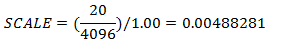
In other words, when GEN_SCALE = 1.00 and the ADC has 12-bit precision (212) and a 20Volt range, the individual ANALOG:SCALE value must be 0.004883 to scale the analog data in the C3D file in volts measured at the ADC input. It is worth noting that, calculated in this manner, the value 0.00488281 volts is the minimum change in input voltage that is required to increase the ADC output count by one. This is another way of saying that the smallest input voltage change that we can detect and record (for the configuration described above) is about 0.0049 volts or 4.9mV – any signal change less than 4.9mV will not be recorded. This is a limitation of the precision used by the ADC recording method, not something that is inherent in the C3D file format.
There are two ways to increase the measurement sensitivity – either increase the measurement resolution (i.e., use a 16-bit ADC with 216 bits of precision), or add additional amplification to the input signal. Increasing the ADC precision usually means changing hardware and software components of the data collection system and generally affects all the analog channels. This can be both expensive and technically challenging. As a result, the common method of increasing measurement sensitivity is to add amplification to the input signal.
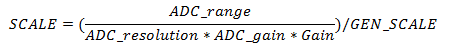
Many modern ADC devices have the ability to internally set gains of x1, x2, x4, and x8 etc. on individual analog channels within the device itself. The gain applied to each analog channel internally will directly affect the ADC_range variable for each channel. For instance, an ADC channel with a nominal ±10 volt input range and an internal ADC_gain of x2 would have an effective input range of ±5Volts due to the additional amplification. The internal ADC_gain for each individual analog channel can be factored into the ANALOG:SCALE parameter thus:
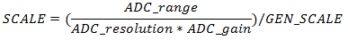
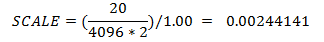
Using the example of an ADC_gain of x2, will cause the ANALOG:SCALE parameter calculated earlier to be reduced by a factor of 2, thus:
In addition to the internal ADC_gain discussed above, many signal sources may have additional amplification that needs to be taken into account – for example, an electromyography system with an amplification of x5000 would produce an output level of ±5 Volts from an input of ±1mV or ±0.001 Volt. This additional Gain can also be factored into the individual ANALOG:SCALE calculations as follows:
 Calculating SCALE values for EMG
systems
Calculating SCALE values for EMG
systems