Calculating SCALE values for force plates
The method used for calculating the SCALE values for force plate channels depends on the force plate type as recorded by the parameter FORCE_PLATFORM:TYPE. The C3D parameters described here accommodate two types of force plate, eight-channel piezo-electric force plates (e.g. Kistler), and six-channel strain gauge force plates (e.g. AMTI, Bertec and Kyowa-Dengyo).
A strain gauge force platform manufacturer will typically supply data with each force plate that describes how the values measured are affected by the applied forces and moments. This information may be in the form of a single value for each output channel, or alternatively as a matrix of values, which describes how every channel affects every other channel. If we use only the diagonal entries from the calibration matrix then we are ignoring cross-talk terms, which are usually quite small when compared to the elements on the matrix diagonal, and we have just a single sensitivity value for each channel. This is the method used for the six-channel force plates that will be describe first since they are the most widely used.
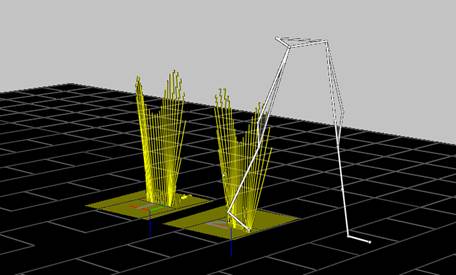
Figure 34 - Force Vectors displayed
The C3D format defines a number of different force plate types to enable the stored analog data from each type to be treated appropriately. TYPE-1 plates have three force outputs (Fx, Fy and Fz) and an Mz and center-of-pressure output (Px and Py). TYPE-2 plates provide three force outputs and three moment outputs (Mx, My, Mz) and scale these signals using a single scaling factor applied to each analog channel. TYPE-3 force plates provide force outputs from the force plate corners while TYPE-4 force plates are similar to TYPE-2 but use the entire cross-talk matrix to scale the output data.
For example, a TYPE-2 force plate sensitivity matrix looks like this:
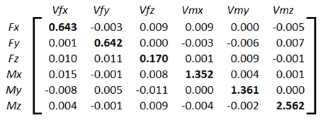
The matrix is ordered as Fx, Fy, Fz, Mx, My, Mz with all values in terms of microvolts produced per Newton, per volt of excitation applied to the force plate strain gauges. Since this is a strain gauge force plate, the actual output level from each channel is dependent on the excitation voltage applied to the strain gauge bridge. Typically, the excitation voltage (ex in the equation below) is in the range of five to ten volts.
If a matrix was not supplied then we would be given just the six major diagonal elements from top left to bottom right (bold in the illustration) which are the only parts of the matrix that are used in calculating the SCALE values for TYPE-1 and TYPE-2 force plates.
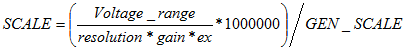
The ANALOG:SCALE value for the first channel (Fx above), will be given by the expression:
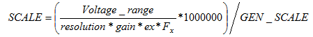
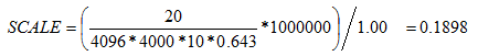
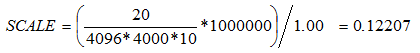
Where Voltage_range is the total ADC input range in volts (e.g. “20” for an ADC with an input range of ±10 Volts), resolution is the total ADC resolution in bits, ex is the platform excitation voltage, and gain is the gain setting on the force platform amplifier for that particular channel (in this example, x4000). The calculated result must be multiplied by 1000000 since the calibration matrix values are supplied in microvolts (μV).
Note that different channels may have different Voltage_range and gain values. These will depend on the type of hardware, and the hardware and software settings in effect when the data were collected. Since the values of these settings are used in the force plate scaling calculations it is vital that they are not changed once the calculations have been performed and the results used to scale the recorded data. As with all analog SCALE values, the GEN_SCALE parameter is included in the calculation:
The application of this scale factor to the stored analog data (see the analog scale calculations for details) will result in an output having the units of newtons applied. Note that you must enter all force plate ANALOG:SCALE factors as negative values to produce an output in terms of reactive force.
If the calibration values are supplied in units of Newton-meters per volt for the force moments, and the measurement units specifying the locations of your reference markers are in millimeters, then you must convert the values referring to moments to Newton-millimeters per volt. This conversion is achieved by multiplying the ANALOG:SCALE results for the moment channels by 1000.
TYPE-3 force plates (Kistler piezo-electric plates) do not use a cross-talk matrix, or produce any moment outputs. Instead, these plates provide eight force channels with outputs that are measured using electrical charge in terms of pico coulombs (pC) per newton applied.
The ANALOG:SCALE values for TYPE-3 force plate are calculated using information provided by the manufacturer about the sensitivity of the force plate transducers, together with the, user-controlled, channel gains of the charge amplifier supplied with each force plate. TYPE-3 plates produce three sets of force output signals, each with a separate calibration value – these are Fx1-2, Fx3-4 and Fy1-4, Fy2-3 together with Fz1, Fz2, Fz3, and Fz4. Each force plate is supplied with three separate calibration values that apply to the Fx, Fy, and Fz channels e.g.
Fx 7.87 pC per Newton
Fy 7.85 pC per Newton
Fz 3.89 pC per Newton
Using the example above with a calibration of 7.87 pC/N and a charge amplifier range of 5000pC (fs_range) for a 10 volt output yields a scale factor would be:
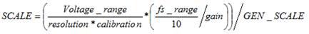
Where resolution is the ADC resolution (4096 for a 12-bit ADC), Voltage_range is the ADC input range, and gain is the individual analog channel gain (if any). With a GEN_SCALE of 1.00 this gives:
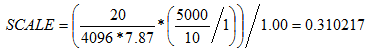
Thus, the Fx SCALE value is 0.310 newtons per volt, which is entered as a negative value to produce an output in terms of reactive force.
TYPE-4 force plates are mechanically and electrically identical to TYPE-2 force plates but use the entire calibration matrix to calculate their output. As a result, the output from a TYPE-4 plate is slightly more accurate then when only the major diagonal information is used. The ANALOG:SCALE parameters for TYPE-4 plates are calculated as follows:
The calibration matrix (the inverse matrix of the sensitivity matrix used by TYPE-2 force plates) should be entered in the FORCE_PLATFORM:CAL_MATRIX parameter. The conversion from volts to newtons will occur when the calibration matrix is applied to the data as an additional step.
Note that different force plate channels may have different voltage ranges and gains. These will depend on the type of hardware, and the hardware and software settings in effect when the data were collected. If the calibration values are supplied in units of Newton-meters per volt for the force moments, and the measurement units specifying the locations of your reference markers are in millimeters, then you must convert the values referring to moments to Newton-millimeters per volt. This conversion is achieved by multiplying the last three rows of the calibration matrix by 1000.
A sensitive test of the force plate performance may be carried out using a stick about one meter long with markers at locations a short distance from either end. After the video system has been fully calibrated, force and 3D data is collected while one end of the stick is placed on the force platform and a force directed along the stick is applied to the upper end of the stick. The upper end of the stick should be moved while the force is continually applied in order to create varying angles of the stick with the FP surface. If the force platform is correctly set up, the force vector and a line joining the two markers should coincide for the full range of motion of the stick.