The Header Section
A 512-byte block is found at the beginning of all C3D files, referred to as the Header Section. The first 12 words of the header section form a record containing basic information about the contents of the C3D file.
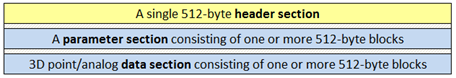
Figure 2 - The header section within the C3D file structure
Applications start accessing a C3D file by reading the header section to locate the parameter section and determine the formats used to store data in the C3D file. Once the header and parameter sections have been read, all the information necessary to start interpreting the C3D file data is accessible.
The information in the 12 word C3D header record, located at the start of the header section, provides information enabling applications to open a C3D file to determine the structure of the file and start reading the contents, e.g.
The location of the parameter records that describe the file contents.
The format used to store 3D data in the data section.
The number of data samples stored within the data section.
The location of the start of the 3D data section records.
The majority of values stored in the C3D file header record are copies of parameters stored in the C3D file parameter section that define the contents of the 3D data section, allowing software applications to retrieve information about the structure and location of data stored within the C3D file. Once the parameter section location is known, applications can determine the endian format, required to interpret all integer and floating point values, calculate the total file size, and interpret the C3D file contents.
All 3D data section samples are stored as integer or floating-point values, a choice defined by the sign of the header SCALE value. A positive SCALE value indicates that the data is stored using signed 16-bit integer values, while a negative SCALE indicates that the data is stored as 32-bit floating-point values.
The header section also supports the storage of 18 unique events that record the time that each event occurs from the start of the first frame of data, as defined by the 3D sample rate. While these events may document incidents that occur during the data collection, they are typically added to the C3D file to document events that are determined by post-collection analysis of the data.
The C3D header section is always the first 512-byte block in the C3D file and is counted as block number one (1) in the C3D file, containing 256 16-bit words with the following structure:
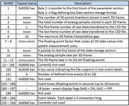
Figure 3- The C3D file header section organization defining 3D Point data storage.
Note that the C3D header contains a number of areas that are marked as Currently not used. Any application that copies, or edits a C3D file, must preserve these areas to guarantee future compatibility while all applications creating new C3D files must set these values as zero (0x00h).
The endian format used in the C3D file must be determined in order to read the C3D file contents because the endian format affects the interpretation of all 16-bit integer and floating-point formats. All applications opening a C3D file must determine the endian type before reading any integer or floating-point values.
The first word in the C3D file must be read as two bytes so that they are unaffected by the C3D file endian format. The first byte is a pointer to the location of the parameter header record at the start of the parameter section, which defines the endian format of the C3D file.
In the hex byte dump example shown in Figure 4, the first byte is 0x02h indicating that the second 512-byte block in the file is the start of the parameter section. The C3D header section is always block 1, the first 512 byte block in the file, and the parameter section block is normally block 2 as in this example. The location of the parameter section can vary and must be determined by reading the first byte of the file which points to the 512 byte block that contains the C3D parameter records that describe the data stored in the C3D file.
The second byte in the C3D file is an identification allowing applications to verify the data section format – this byte is normally 0x50h (an ASCII ‘P’ character) that documents that the C3D file uses the defined 3D Point data format to store multiple 3D point locations as XYZ coordinates, synchronized with multiple 16-bit analog sensor data samples.
When the second byte of a C3D file is 0x50h (80 decimal, the ASCII “P” character) the C3D file stores 3D point locations and analog data in a structure described by the following eleven 16-bit words. This has been the default C3D data storage method since the format was first described in 1986.
The second word in the C3D file 3D Point header is an unsigned integer that records the number of trajectories stored in each frame of the file as 3D points – this is a copy of the POINT:USED parameter, stored as an unsigned integer. The C3D file 3D Point structure supports data records containing 3D locations stored with related analog samples, the file header example below documents that the file contains 26 3D points (stored as 0x1A00 hex - big endian)
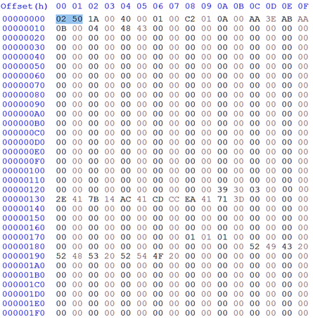
Figure 4 - A hex dump of a typical little endian C3D 3D Point header section.
The third word in the C3D file 3D Point header is an unsigned integer that contains the number of analog samples stored with each frame of data in the file – each sample consists of a 16-bit data value per 3D frame. The example above contains 64 analog samples per frame, note that this is the number of stored samples per frame, not the actual analog sample rate which is always an integer multiple of the 3D point rate to guarantee synchronization between the analog and 3D point data samples. If the third word is zero then the C3D file contains 3D Point samples but does not contain any analog data samples.
All motion capture systems that collect 3D data typically record images from multiple camera or sensor sources, and use photogrammetry methods to calculate the observed 3D locations from multiple 2D images. Once these 3D point calculations have been performed, the C3D file can be generated from the sampled data. The 3D frame range of the data transferred to the C3D file is normally written in the next two header words as two unsigned 16-bit integers, recording the first frame number and the last frame number of the raw data that generated the C3D file. The two frame numbers are written as unsigned integers using a 1-based count (there is no frame 0) and have a maximum value of 65535 frames.
Although these two header entries are often interpreted as C3D frame numbers this is incorrect, these are actually the frame numbers of the raw data that was used to create the C3D file, not the C3D frame numbers. All C3D file data should be referenced in the range of 1 to n – as a result, files containing exactly 1000 frames may be found with frames recorded in the header with ranges such as 1 to 1001, 23 to 1024, or 20,005 to 21,006 etc. Since the header frame numbers refer to the raw data file used to create the C3D file, they fail to define the C3D frame range if the photogrammetry process drops any frames during the C3D file creation process.
The raw data frame range stored in the C3D file header section is not stored in the parameter section because the recorded frame range was originally included for reference only, documenting the raw data frame range used to create the C3D file, not the frame count in the C3D file. In the example shown in Figure 4, the two words are 0x0100 hex and 0xC201 hex which are read as two big endian unsigned integers i.e., frames 1 to 450, documenting the original raw data source frames that were used to create the C3D file.
The number of frames in a C3D file is defined by the POINT:FRAMES parameter but applications occasionally attempt to determine the number of frame in a C3D file by subtracting the header start frame number from the end frame number, so these values may need to be maintained when C3D files are created to maintain compatibility with older applications. Applications needing to synchronize the contents of the C3D file with external video files should create the optional TRIAL parameter group to record the start and end frames as floating-point “field” numbers providing a full synchronization range with external video files.
3D Point header word six is an unsigned integer that contains a value that stores the maximum interpolation gap length for 3D Point data. The use of this item is not specified in the C3D file description although the maximum interpolation gap length value is usually set to indicate the maximum length of potentially invalid 3D point data samples (in frames) over which 3D point interpolation may be performed. This may be used by various applications to specify the length of gaps that can be interpolated or gap filled when reading or creating a C3D file. Since the value of the maximum interpolation gap is recorded in 3D frames, it represents time but does not indicate that any 3D data points have been interpolated. Any application reading the C3D file may override this value and interpolate gaps of any length if desired and record the maximum interpolation length by updating this value.
Words 7 and 8 in the C3D file 3D Point header contain a copy of the 3D scale factor stored as a 32-bit floating-point value. This parameter is required when 3D data values are stored using the standard signed integer format because it is used to scale each of the stored 3D point and residual values from signed integer values to physical world values. When 3D data is stored as scaled floating-point values, it is used to scale the 3D residuals which are recorded as integers, so it is essential that a correct 3D scale factor is calculated for all C3D formats. Failing to calculate a valid 3D scale factor causes data corruption when a floating-point C3D file is converted to the default integer format required by many user written applications.
The format of the 32-bit floating-point value storing the 3D scale factor depends on the C3D file endian format so all applications reading a C3D file must determine the C3D file processor type before interpreting this value.
The sign of the 3D scale factor is used to determine the 3D point and analog data storage method (floating-point or signed integer). A positive scale value indicates that the C3D data section is stored as one’s complement signed 16-bit integers; a negative scale value indicates that the data section is stored as scaled 32-bit floating-point values. If a signed integer C3D file is converted to floating-point format then the original 3D scale factor should be simply negated and stored – this allows transparent conversion between signed integer and floating-point data types unless the floating-point data is modified in some way.
To retain the maximum resolution for signed integer data, the 3D scale factor should be the maximum absolute coordinate value stored in the file, divided by 32000. This will allow all of the 3D point coordinates to be safely stored within the range of a signed 16-bit integer value with maximum accuracy.
Header word 9 is a copy of the DATA_START parameter – this is stored an unsigned integer that points to the first 512-byte block in the C3D file that starts the 3D point and analog data section. The 512-byte blocks are counted from the start of the C3D file with the 512-byte C3D header section counted as block 1.
The original use of a signed integer, required by FORTRAN in 1986, limited the maximum value of DATA_START to 32767 in old C3D files. As C3D files because larger the interpretation of the POINT:DATA_START value was change to be read as an unsigned integer value extending the potential start location of the 3D data section within the C3D file.
Header word 10 stores the number of analog samples associated with each 3D frame. If the C3D file does not contain any analog data then this will be zero. If the C3D file contains analog data then it will be interleaved with the 3D data to ensure that synchronization is maintained between the 3D and analog samples. The C3D structure for 3D point and analog data samples assumes that each 3D frame can have one or more analog samples from each channel sampled (as determined by the count stored in the third word of the C3D file header). Thus the actual analog sample rate is measured and recorded in terms of analog samples per 3D frame.
While this means that C3D files can only contain data sampled at integer multiples of the 3D frame rate, it means that data storage synchronization is guaranteed and makes it easy to calculate the size and location of individual 3D data frames and their associated analog samples within the C3D file.
Header words 11 and 12 record the 3D frame rate in samples per second – commonly thought of as Hertz (Hz.). Note that the 3D frame rate parameter is a floating-point value, making it possible to accurately record the 3D frame rate for video based sampling systems. For instance most 60 Hz, video based systems, actually sample the video data at 59.94 Hz which, while close to the commonly assumed exact 60.00 Hz sample rate, can introduce synchronization errors between the video and the analog data at the end of trials if the correct value is not recorded.
C3D file header words 13 – 149 are currently not used and may provide additional expansion features in the future. Applications that create new C3D files should fill these words with 0x00h, while applications that copy or edit C3D files must preserve the contents of these words.
Header words 150 and 151 in the C3D file header are used by the header event storage feature. The header event storage allows the timing of a maximum of 18 events to be recorded in the C3D file header section. Header word 151 stores the number of events stored in the C3D header – this can be any signed integer value between 0 and 18. Words 153 through 234 are used to store up to 18 event times together with a four-character label and a status (either ON or OFF) for each defined event. Events defined in the header may be used for any purpose although in gait analysis they are typically used to indicate gait cycle timing. Words 152 and 198 are unused. Events can also be independently stored in the EVENT group in the parameter section of the C3D file – parameter events and header events are independently recorded and there is no requirement that they duplicate each other.
The remaining C3D header section words 235 through 256 are currently not used. Applications that create new C3D files should fill these words with 0x00h while applications that copy or edit C3D files should preserve the contents of these words.
 Header events